evolvBot
Giving AI agents a body in the physical world.
An extensible platform where an agent designs, fabricates, and grows the body it needs — imagining in simulation, printing components, ordering parts. The first build works: it finds a TV remote and puts it back on the table.
Read the briefToday's AI agents think and act in software. evolvBot gives them hands.
Perception and reasoning have outrun embodiment. evolvBot is the platform where an agent doesn't just use a fixed body — it designs, fabricates, and grows the body it needs to finish a job, then tests the result against reality.
Enable AI agents to fully operate in the physical world.
Agents that act on matter, not just bits.
An extensible platform for an agent to evolve its physical self.
By printing components, ordering parts, and imagining solutions in simulated worlds.
An agent that extends its own reach, in simulation.
The smallest honest slice of the vision. A minimal robot body has a target it cannot reach. Claude imagines a bolt-on extension; a PyBullet simulator tests it; the result feeds back; the agent refines until it reaches — one closed loop, need → design → test → evolve.
Read the full implementation plan →A single revolute joint with a straight rigid extension can't change its radius — the effective tip traces a circle of radius L + d. To hit a target at radius R, the agent must design d ≈ R − L: too short and too long both miss. That forces precision (not "long enough"), makes both error directions meaningful feedback, and makes minimizing material a real objective.
Six small units, each with one job and a clean interface. The Claude call sits behind a Designer protocol, so the whole loop runs — and is fully tested — with no API key.
| Module | One job | Interface |
|---|---|---|
body.py | Define the minimal body + attachment interface | Body, MountFrame, forward_kinematics(θ) |
problem.py | Compose a task | Problem(body, target, constraints) |
part.py | Spec → geometry + artifact | build_part(spec), export_stl() |
sim.py | Test a part in PyBullet | test(problem, part) → TestResult |
designer.py | Propose the next part | ClaudeDesigner · FakeDesigner |
loop.py | Orchestrate the cycle | run(problem, designer, max_iters) |
Phase 0 deliberately defines the minimal body and the attachment interface where every future part bolts on — the seam the whole platform is built around. A part fixes rigidly to the MountFrame; its far end becomes the new effective end-effector. In Phase 2 a real mechanical connector maps onto this same frame.
Ranges are validated client-side with Pydantic (the structured-output API ignores min/max); an invalid or unbuildable spec becomes a failed attempt with feedback, never a crash. The reach test is a deterministic θ-sweep (1° steps) over the joint range — no IK solver — so it's trivially unit-testable.
- claude-opus-4-8 via the Python
anthropicSDK. - Structured output —
messages.parse(output_format=PartSpec); every proposal is a validated spec. - Adaptive thinking —
thinking={"type":"adaptive"},effort="medium"for the "imagining." - Prompt caching — the stable system prompt is cached; only the per-iteration attempt history varies.
- Feedback — each round, a plain-language critique derived from
TestResult("short by 8.2 cm", "overshot by 3.0 cm").
FakeDesigner returns scripted specs, so loop, sim, and part are tested offline, $0, CI-safe: d=15cm → reached, d=5cm → short, d=30cm → overshoot; [short, correct] → reaches on iteration 2. The only non-deterministic seam — ClaudeDesigner — is one key-gated smoke test.
- Loop closes on a real reach in ≤ 6 iterations with
ClaudeDesigner. - Every iteration logs the spec + rationale + feedback.
- Exports a print-ready .stl of the winning part and a GIF of the reach.
- Deterministic tests pass with no network access.
All tooling is free/open-source; the only metered cost is the Claude API — a few cents per full run, $0 on the offline FakeDesigner path.
Built end-to-end in simulation — it finds the remote and puts it back.
The full loop runs as one pipeline: perceive → navigate → evolve the arm (within budget) → grasp → place. The minimal robot can't reach the floor, so it designs a longer arm, orders the parts, swaps it on, and finishes the job — all offline, $0, with 51 tests green.
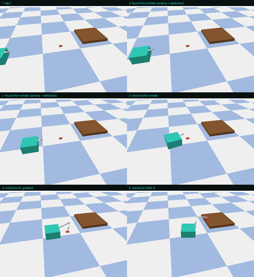
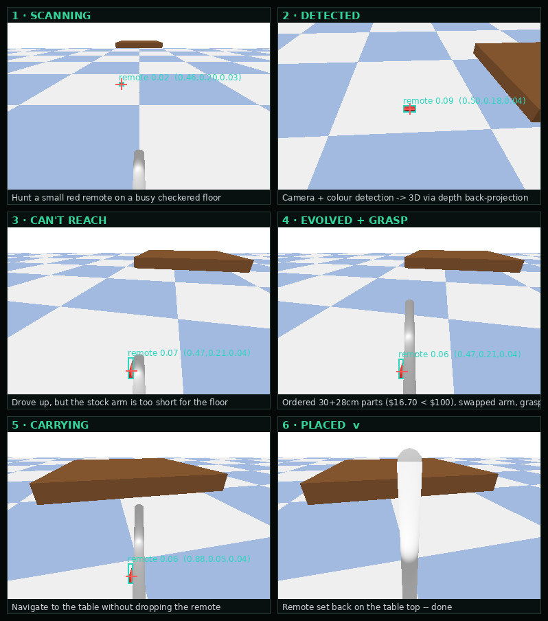
Everything above runs in a PyBullet simulation. The two real-world hooks are built but gated: a Claude-vision detector (Claude reads the frame instead of colour-thresholding) runs with an API key, and a real Bambu X1 print generates the STL here but only prints from the home environment on an explicit OK.
Then we made the contact real — and taught it to clean a window.
We ported the world to MuJoCo so grasping is physical, not a kinematic weld: the jaws close, friction carries the object, gravity settles it. Two new acceptance tasks prove it — both shown here from the robot's own onboard camera. The arm is a plain serial chain — a shoulder yaw, then shoulder, elbow and wrist pitch joints — with a dark housing on each hinge so you can see exactly where it pivots.
Wiping needs sustained sliding contact — impossible to fake with a weld. MuJoCo gives real contact, friction, and metric-depth cameras, so perception reads something camera-like and the hands actually have to grip. Same Claude-driven loop, same three swappable seams (designer · fabricator · detector) — just an honest body.
Now we're building it — a real machine you can print and bolt together.
The simulation above is the digital twin of a physical robot, part-for-part. The basic body is exactly the parts that pass the two acceptances — a 4-DOF arm on a vertical lift with a magnetic tool-changer that swaps a wiper and a gripper, on an ESP32-CAM base. Every chore beyond it is a rung on an evolutionary ladder: each milestone bolts on one new printed or ordered part, and a task can't be attempted until the parts below it exist.
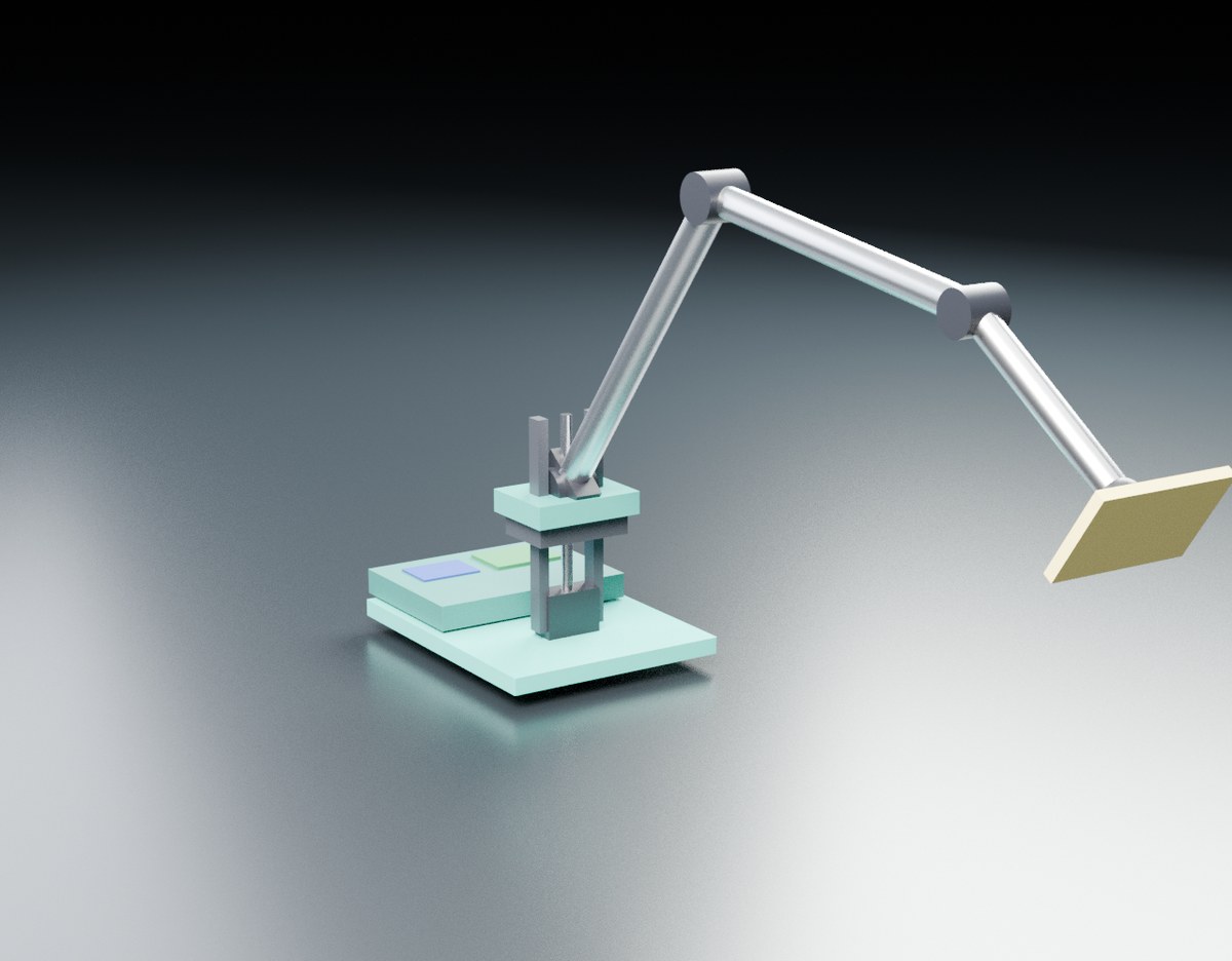
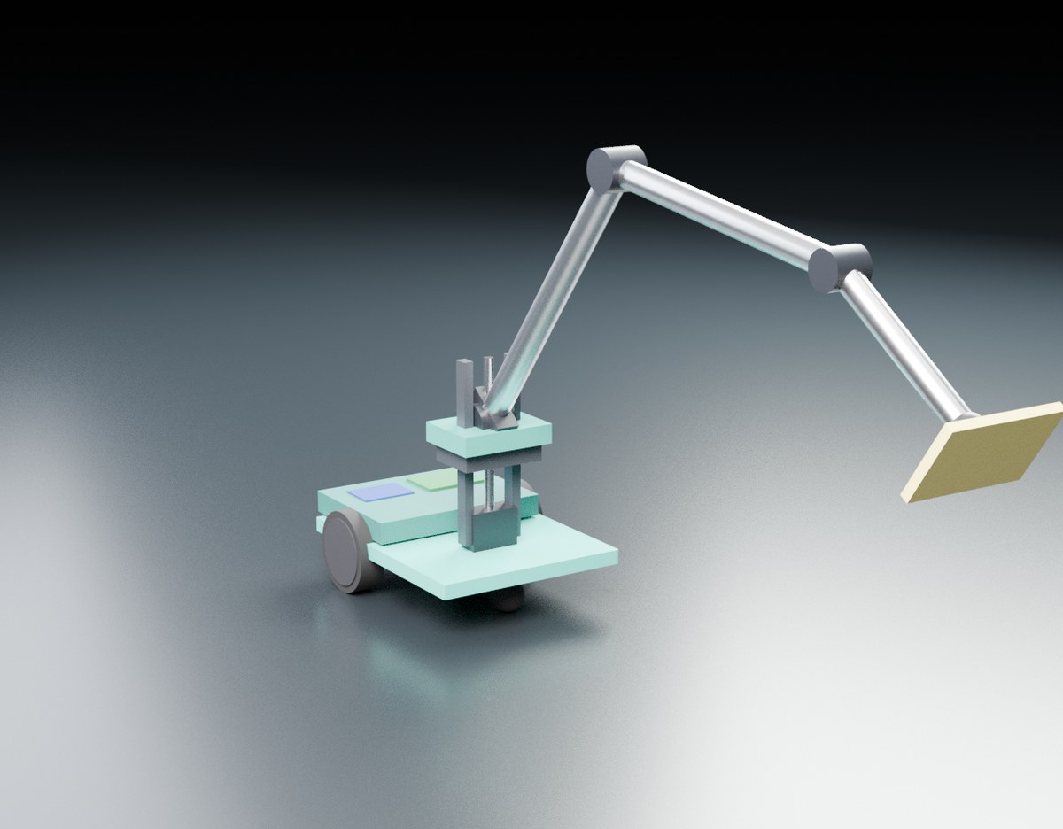
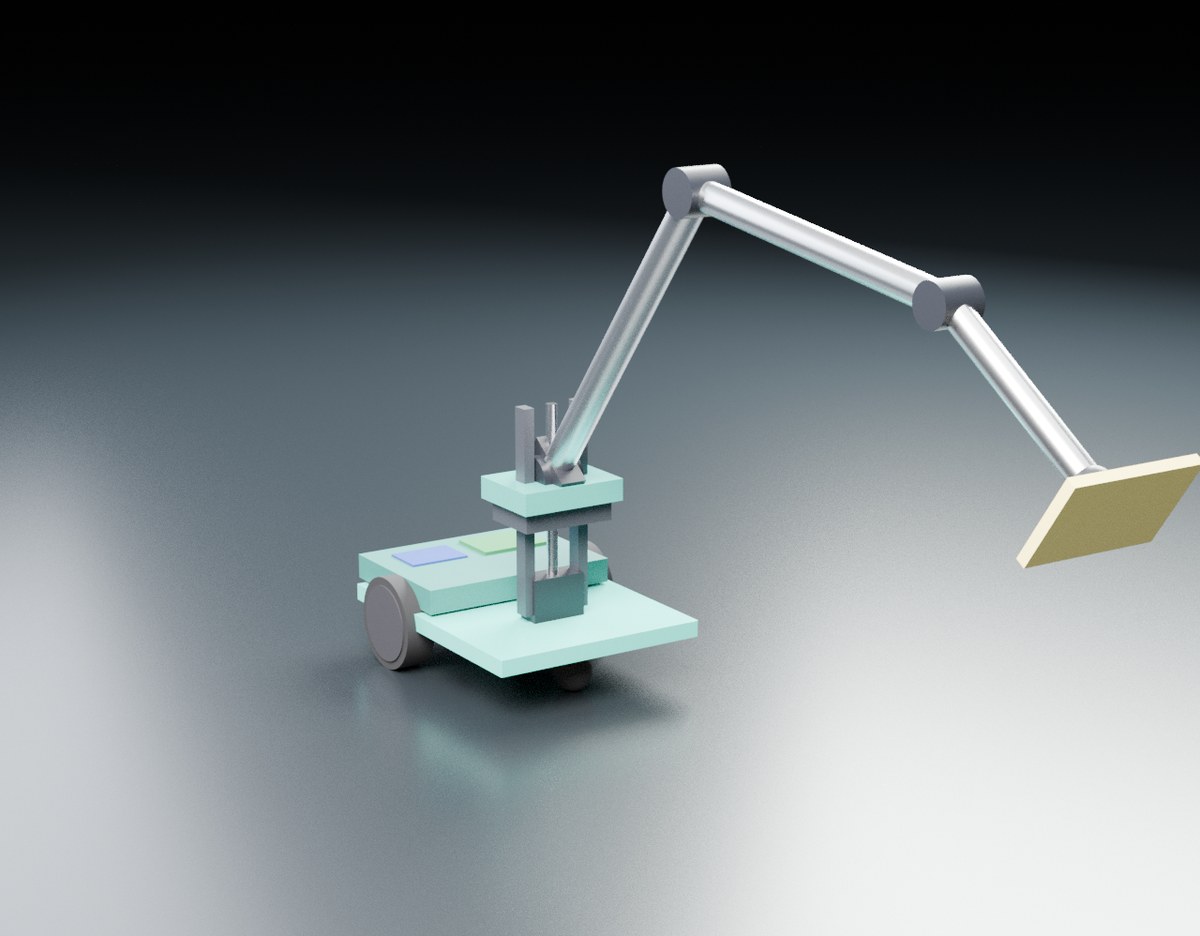
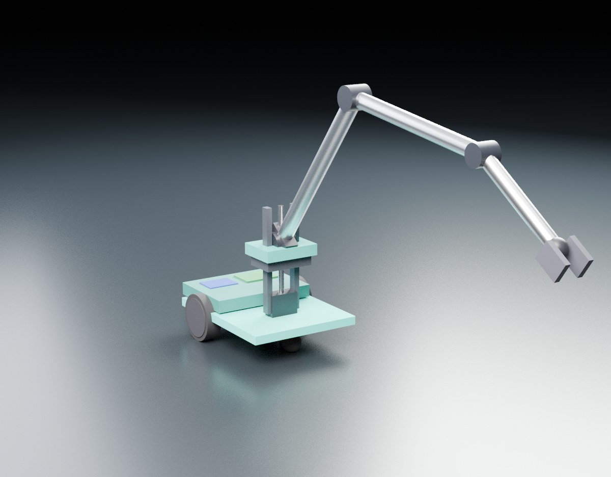
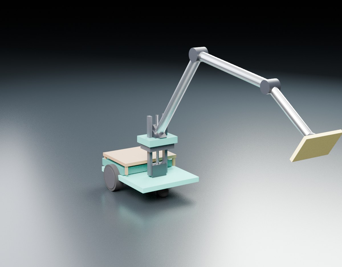
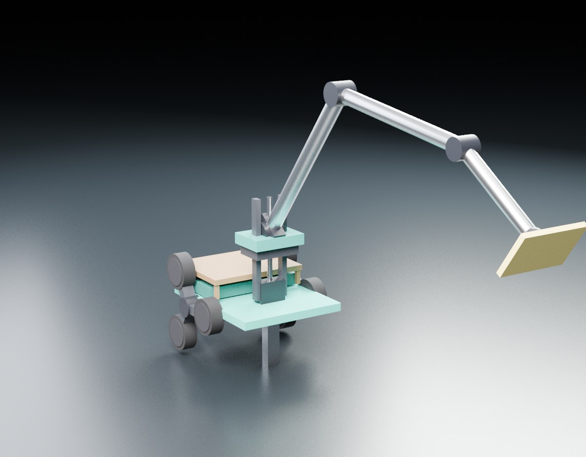
Dependency: M0 → M1 → {M2, M3, M4} → M5. 24 graded tasks double as the physical tests and the milestone steps.
Every line is under $10 and either off-the-shelf or home-printable — the project's budget rule, kept in the real world.
| Part | Qty | ~ $ | Where |
|---|---|---|---|
| Servos — MG996R ×4 + MG90S ×2 | 6 | 26 | AliExpress / Amazon |
| ESP32-CAM (compute + camera) | 1 | 8 | AliExpress / Amazon |
| PCA9685 16-ch servo driver | 1 | 3 | Adafruit / AliExpress |
| MPU-6050 IMU | 1 | 3 | AliExpress / Amazon |
| 6 V 5 A PSU / UBEC | 1 | 8 | Amazon / AliExpress |
| 608ZZ bearings + 8 mm shaft | 1 | 4 | Amazon / hardware store |
| T8 lead-screw + brass nut | 1 | 5 | AliExpress / Amazon |
| Neodymium magnets 6×3 mm | 6 | 4 | Amazon / AliExpress |
| Microfiber pads + compliance foam | 1 | 5 | Grocery / hardware store |
| M3 screws + heat-set insert kit | 1 | 6 | Amazon / hardware store |
| PLA filament (~250 g — all printed parts) | 1 | 6 | Bambu Lab / Amazon |
| Basic body total | $78 | every part < $10 |
- Upgrade path: Feetech STS3215 bus servos (the SO-ARM100 / LeRobot lineage — encoder + position feedback) ~$14 each. Better control, but they break the < $10/part rule.
- Honest budgeting: the ≤ $100 cap is the simulation's per-run budget; M0 fits inside it ($78). The full stair-climbing carrier (M0→M5) is ≈ $172 — a real mobile robot needs motors and a battery, and we say so.
From a sim loop to a self-fabricating agent.
Phase 0 is done — and the simulation above already runs the whole need → design → fabricate → test → place loop end-to-end (the Phase 4 acceptance test, in sim). The rungs below are the path to doing it in the physical world.
Reach, in simulation Done ✓
Minimal body, the attachment interface, the agent-driven design loop, and a real STL artifact.
A richer design space
Multi-segment parts and obstacles; a growing library of learned components.
Close the sim-to-real gap
Slice and actually print the winning part; verify it on real hardware.
Order what it can't make
The agent sources parts from vendors and extends its own embodiment.
The full platform
A human states a goal; the agent does whatever it takes — imagine in sim, fabricate (print or order), test in reality, iterate — until it's met.